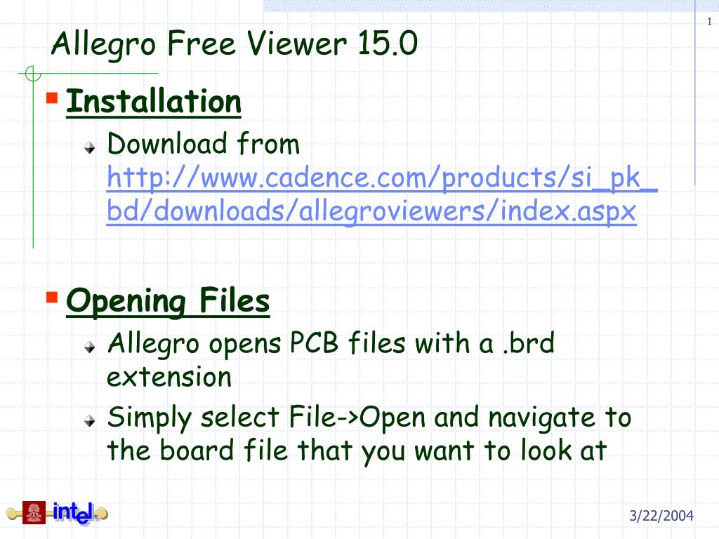
.brd - Board database file–typically the printed circuit board (PCB) design file that you add symbols and a net list to when designing the board.
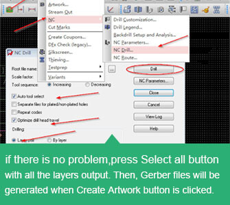
Different PCB design software feature different operation steps of PCB Gerber files generation. In the following part of this article, We will show you how to generate PCB Gerber file from Cadence Allegro in details. Open your PCB layout in Cadence Allegro: 1. First, manually add artwork layers, and then click ManufactureArtwork. Creating a PCB Design OrCAD / Allegro PCB Editor Nordcad Systems A/S / Nordcad AS 2018 +45 96 31 56 99 / +47 21 55 - R2 support@nordcad.dk / support@nordcad.no 28 28 Page 2 of 31 Importing the schematic design into the board template The guide will use a template that’s already been designed, if you’re interested then appendix A. The design tools for the i.MX6 SABRE SD board were OrCAD and Allegro, so, only these.dsn and.brd files are available on our side. Unfortunately, there seems to be no easy way of converting.brd to.pcb files. Seems that you should have both Allegro and PADS tools installed to make the conversion. For more information, please refer to attached. Click Browse to Open the the.xml file from your Downloads Folder. Select Open-Library from the File menu. Select the the.OLB file from your Downloads Folder and click Open. Double-click the symbol name (Manufacturer Part Number) to preview the Symbol. Allegro PCB 17.2 or later. Select Open from the File.
.dra - Drawing file–graphics that can be graphically edited and used to create the binary symbols that are used in the .brd file.
.mdd - Module definitions–sections of a board design that include package symbols and logical connections.
.bsm - Mechanical symbol (board symbol) that gets added to a board with no logic attached.
.osm - Format symbol, (other symbol)–typically graphics, notes,drawing format, notes, logo’s.
.ssm - Shape symbol–when a pad is an irregular shape (not a circle, square, rectangle, and so on).
.fsm - Flash symbol–used to define a thermal relief pad. There is an editor that helps you automatically create these.
.scr - Script or macro file–an ASCII text file containing Allegro commands that can be replayed to reproduce the same results as if you were selecting those commands.
.tech - Technology file–ASCII file of constraints and design rules.
.mcm - Multi-chip Module File (APD) A design file similar to an Allegro.brd file, but different technology
.txt - Text file, such as that used for parameters. Device files are .txt that contain the definition of a logical device including device type, package symbol, pincount, functions, and swappability.
.jrl - A journal file contains a record of events—menu picks,keyboard, and so on—which are recorded for each session in Allegro.
.INI - This file keeps track of the path your working file is in. The.INI file also keeps track of the window location, the toolbar,and the status of whether the Control Panel is docked and it's location. DO NOT EDIT THIS FILE, if you are having problems with Allegro. This file can be deleted as a form of troubleshooting. The file will be recreated automatically.
How To Open .pcb File In Allegro
.geo - This file remembers the location of forms the last time they were used and places the same type of form in the same location the next time it is used. DO NOT EDIT THIS FILE!
.color - Color view—defines which subclass graphics will be visible or invisible.This file is automatically created when an artwork film control is defined or can be user defined.
******************* Kumargs *******************
How to include our free library content in your OrCAD/Allegro Libraries.
OrCAD/Allegro 17.2 or later with Library Loader V2.37 or later
1. Click Settings in Library Loader
2. Select “Allegro 17 or later” from the Version drop-down. Then set the paths by clicking the browse buttons for the padpath (folder containing the padstack (*.pad) files, psmpath (folder containing the package symbol (*.psm) and package drawing (*.dra) files, and steppath (folder containing the 3D STEP (*.stp) files.
Note: These paths can be determined by reviewing them in the Allegro User Preferences Editor (“User Preferences….” from the Setup menu in the PCB Editor)
3. To prevent these instructions from showing every time you download a part, please uncheck “Show Library Import Instructions”. If you want to review these at any point, you can click the Help link in the same dialog.
4. Click OK to accept the Settings
OrCAD Capture 17.2 or later
1. Select Import->Library XML from the File menu.
2. Click Browse to Open the the *.xml file from your Downloads Folder. Then click OK.
3. Select Open->Library from the File menu.
4. Select the the *.OLB file from your Downloads Folder and click Open.

5.
5. Double-click the symbol name (Manufacturer Part Number) to preview the Symbol.
Allegro PCB 17.2 or later
1. Select Open… from the File menu
2. Browse to your psmpath and select the Symbol Drawing (*.dra) for the downloaded part. Note: If you are unsure of the name it can be found in the value of the “PCB Footprint” package property of the OrCAD Capture symbol. Then click Open.
3. If the downloaded part included a 3D model, select “Step Package Mapping…” from the Setup menu
4. Review the pre-selected Primary Model and then click Save followed by Close.
5. Select “3D Canvas” from the View menu.
Library Loader V2.36 or earlier
1 – Click Settings in Library Loader.
2 – Select the appropriate version
3 – To prevent these instructions from showing every time you download a part, please uncheck “Show Library Import Instructions”. If you want to review these at any point, you can click the Help link in the same dialog.
4 – Click OK to accept the Settings
OrCAD Capture
1 – Select Import->EDIF from the File menu.
2 – Click Browse to Open the the *.edf file from your Downloads Folder. If the “Configuration file” is not preset to the EDI2CAP.CFG from the OrCAD installation directory, you will also find this file in your Downloads Folder. Then click OK.
3 – Click OK to accept the warnings.
4 – Select Open->Library from the File menu.
5 – Select the the *.olb file from your Downloads Folder and click Open.
6 – Double-click the symbol name (Manufacturer Part Number) to preview the Symbol.
Allegro PCB
IMPORTANT! – You must ensure that your Downloads Folder is included in the Library padpath:

1 – Select “User Preferences….” from the Setup menu in the PCB Editor. Click the Browse (…) button against padpath under the Paths->Library Category.
2 – Click the “New (Insert)” icon and then click “…” to browse to your Downloads Folder. Then click OK.
Start here if padpath includes your Downloads Folder.
Allegro Pcb Editor Tutorial
1 – Double-click the BuildFootprint.bat file from your Downloads Folder.

2- If the downloaded component has D-shaped pads, the d-shape.scr script will run first to generate the d-shape drawing. Once this has finished, select “Zoom Fit” from the View menu to preview. Then click the cross (X) in the top right corner or select “Exit” from the File menu to close the editor.
Allegro Pcb Viewer
3 – The scripts will continue to run to generate the required padstacks and then use these to build the footprint. Once this has finished, select “Zoom Fit” from the View menu to preview. Then click the cross (X) in the top right corner or select “Exit” from the File menu to close the editor. Click Yes to save changes.
4 – Click the cross (X) in the top right corner of the command prompt.
5 – Done

Comments are closed.